
Fiber Optics
Fiber optics are used as a data transmission method whereby data is converted into modulated waves of light to be sent over optical fiber cable. Fiber optics are an alternative to traditional copper based data transmission cables over which they possess several advantages such as extremely high bandwidth, low losses even over great distances and inherent resistance to EMI.
“ It would take thousands of metal-based wires to replace one single fiber optic wire ”
How It Works
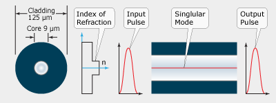
Light is transmitted through the core of a fiber optical cable by bouncing off the walls of the cladding by the principle of total internal reflection allowing the fiber to act as a light waveguide. Because the cladding does not absorb light from the core, signals can travel great distances with only slight losses occurring from impurities in the glass. Fiber cable can be made to support a single propagation path (single-mode fiber) or multiple propagation paths (multi-mode fiber).
Some History
The birth of fiber optics dates back to the first demonstration of guiding light by refraction by Daniel Colladon and Jacques Babinet in early 1840s France. The first practical applications of optical fiber appeared early last century when it was used for internal illumination during dentistry procedures. It was not until 1965 though that fiber finally hit its potential when Charles K. Kao [Factoid: Nobel Prize recipient in Physics 2009] and George A. Hockham, of the firm Standard Telephones and Cables, proposed that optical fiber could be effectively used for telecommunications by removing impurities within the optical glass to reduce the signal attenuation to below the threshold of 20 dB/km. By the mid-seventies, doped optical glass produced by Corning yielded attenuation levels of just 4 dB/km.
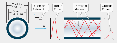
Multi-mode Optical Fiber Detail
The first generation of deployed fiber came about in 1977 using GaAs semiconductor lasers to achieve a bit rate of 45 Mbps with repeater spacing of up to 10 km. A major milestone for fiber occurred in 1988 when the first transatlantic telephone cable to use optical fiber, the TAT-8, went into operation. Since then, the use of fiber has exploded to encompass virtually all long distance telecommunications within the United States. In fact, the Internet as we know it today would not have been possible without a massive fiber optic infrastructure to carry the burden of such a high data through fare.
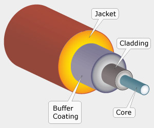
Optical Fiber Construction
Optical fiber cable is constructed by two dielectric layers: a core which is surrounded by cladding. In order to confine the light signal within the core, the core's refractive index must be greater than the cladding's. The physical boundary between the core and cladding is an abrupt change in step-index fiber and a gradual change for graded-index fiber. Both the core and cladding are fabricated from silica glass which has a typical refractive index of 1.5 [Factoid: The refractive indexes of the core and cladding typically differ by a mere 1%]. Surrounding the cladding is a buffer coating comprised of UV-cured urethane acrylate composite. Finally, a cable jacket layer acts as the last form of protection for the fiber cable from the environment.
Unlike metal-based electrical connections, combining lengths of fiber optic cable is a complex and delicate process. Care and special tools are needed to cleave the ends at the appropriate angle which is followed by either a mechanical connection or by fusing the ends with an electrical arc. For mechanical connections, special removable connectors are available exclusively for this purpose.
Civilian Fiber Optic Jacket Color Chart
| Fiber Type | Jacket Color |
|---|---|
| Single-mode | Yellow |
| Multi-mode 62.5/125 μm (OM1) | Orange |
| Multi-mode 50/125 μm (OM2) | Orange |
| Multi-mode 50/125 μm "laser optimized" 10 Gbps (OM3) | Aqua |
Fiber Optics vs Copper Based Signal Transmission
Bandwidth
Fiber optics offer a great many benefits over traditional copper based signal
transmission which has in turn led to their popularity with the
telecommunications industry. One main benefit of optical fiber is its massive
bandwidth. In fact, fiber can often carry so much data that it would take
thousands of metal-based wires to replace one single high-bandwidth fiber optic
wire.
Low Signal Loss
Another benefit of fiber cable is its very low signal loss, which allows for
great distances between terminations or in-line signal repeaters. While
copper cabling typically can run only about a mile before needing
amplification, it is not uncommon for fiber optic cable to run 60 miles
before signal boosting or processing. One reason for fiber's low losses
stems from its lack of electrical conductivity which also means that it
produces zero crosstalk between parallel runs of
cable over great distances. Crosstalk is a chief contributor to signal loss
in metal-based signal wire [Factoid: Cat 5e and Cat 6 cable feature
twisted wire pairs to reduce crosstalk].
Fiber Optic Bandwidth per Cable Size
| Ethernet Data Rate (Gbps) |
Fiber Size (μm) |
Bandwidth @ λ: 850/1300 nm (MHz) |
Bandwidth @ λ: 1310/1550 nm (THz) |
Average Distance (km) |
|---|---|---|---|---|
| 0.1 | 62.5/125 | 200/500 | - | 2 |
| 0.1 | 50/125 | 500/500 | - | 2 |
| 0.1 | 9/125 | - | ≈ 100 | 100 |
| 1 | 62.5/125 | 200/500 | - | 0.22 |
| 1 | 50/125 | 500/500 | - | 0.55 |
| 1 | 9/125 | - | ≈ 100 | 70 |
| 10 | 62.5/125 | 200/500 | - | 0.035 |
| 10 | 50/125 | 500/500 | - | 0.065 |
| 10 | 50/125 VCSELs Optimized | 2000/500 | - | 0.3 |
| 10 | 9/125 | - | ≈ 100 | 40 |
Immunity EMI/RFI
As fiber cables are all dielectric, they are effectively immune to
RFI/EMI. This means that fiber cabling can be run in areas
of high interference such near power lines, utility lines and transmission
antennas. Furthermore, fiber cables are ideal for areas where lightning
strikes are commonplace. In fact, fiber is even immune to nuclear
electromagnetic pulses though it can be damaged by a blast's alpha and
beta particle emission.
Other Advantages
Because fiber cable is lighter than metal based wires, it is ideal for use on
aircraft where weight is always a concern. Safety too is another hallmark of
fiber as its inability to spark due to potential differences make it useful
in flammable environments. Lastly, fiber is very difficult to signal tap
without disrupting the original transmission which makes it a very secure
data transmission method.
Fiber Types
Step-Index Multi-mode Fiber
Graded-Index Multi-mode Fiber
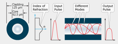
Step-Index Single-mode Fiber
Single-mode
Single-mode fiber cable
is a thin, 9 μm core of glass doped with the element Germanium
surrounded by a thicker layer of pure glass. While it can be used for
nearly any application, single-mode fiber is optimized for near-infrared
light transmission at wavelengths between 1,300 and 1,550 μm from
lasers. This type of cable provides the backbone for the telecommunications
industry in the United States.
Single-mode fiber is designed to transmit only a single mode of light which travels down the length of the cable core. Single-mode fiber optics exhibit a much narrower modal dispersion than their multi-mode cousins which makes them better suited for long distance transmission and higher bandwidths than the latter. Single-mode cables are only deployed to non-local environments due to their requiring powerful and expensive lasers for operation.
Multi-mode
Multi-mode fibers
have large cores (typically 62.5 μm in diameter) and transmit infrared
light (850 nm ≤ λ ≤ 1,300 nm) from LEDs.
Multi-mode fiber is designed for transmission over small distances (< 1 km)
such as within a building or a complex.
Multi-mode fiber's larger core size allows for transmission of multiple paths of light. As each mode travels at its own propagation velocity, multi-mode fiber suffers from modal dispersion which limits the maximum length a signal can be transmitted through it. This shortcoming is made up for by multi-mode's superior light gathering which allows signals to be driven with less powerful light sources such as light emitting diodes or vertical-cavity surface-emitting lasers.
10 Gig Multi-mode Fiber
Society's ever increasing data consumption has led to the development of high-bandwidth multi-mode optical fiber. Otherwise known as "aqua" fiber due to their aqua colored jacketing, these 10 Gig Multi-mode 50/125 μm cables use VCSELs as light sources. Because VCSELs emit less modes than their LED counterparts, bandwidth limitations due to modal dispersion are lessened in 10 Gig fiber optic cables. In fact, Data rates up to a theoretical 10 Gbps are possible with this type of fiber which also provides for full backwards compatibility with older LED based 50/125 multi-mode networks (but at slower speeds).
Fiber Optic Connectors| Connector Type | Picture | Coupling Type | # of Fibers | Application |
|---|---|---|---|---|
| FC | 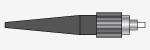 | Screw On | 1 | Telecommunications |
| LC | 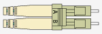 | RJ45 Style Snap On | 1 or 2 | Gigabit Ethernet |
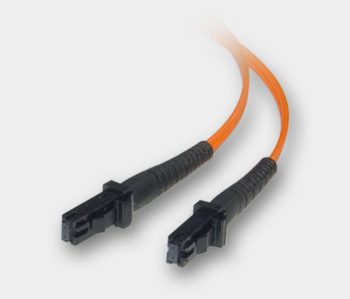
| MTRJ | 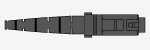 | RJ45 Style Snap On | 2 | Gigabit Ethernet |
| SC |  | Snap On | 1 | CATV |
| ST |  | Twist On | 1 | LANS |
Mixing and Matching Fiber Types and Sizes
Without the proper equipment, you cannot mix fiber types or sizes. Connecting
multi-mode to single-mode fiber cables will result in 20 dB signal losses
which translates to a whopping 99% power loss. Even connecting 50/125 to
62.5/125 cables will result in a 3 dB signal loss which is 50% of the
original power. However, by using mode conditioning cables which avert losses
due to differential mode delay,
single-mode fiber connections can be run over existing multi-mode networks
without significant signal losses.
Common Fiber Optic Networking Products
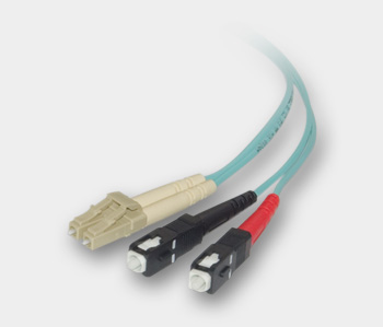
MTRJ / MTRJ, Multimode, Duplex Fiber Optic Cable, 62.5/125, 1 Meter
This riser-rated patch cable features the small form MTRJ connector and its
RJ45-like, latching design which allows for easy connections even in patch
panels with extremely high port density. MTRJ connectors contain two fibers
along with alignment pins to ensure a near-perfect connection. Multi-mode
62.5/125 patch cables with MTRJ connectors are typically used in gigabit
Ethernet and multimedia applications.
LC / SC, Multimode, Duplex Fiber Optic Cable, 10-Gigabit Aqua, 50/125, 1 Meter 10 Gig "Aqua" fiber is ideal for high-bandwidth applications and supports 10 Gbps dataspeeds up to 300 meters. These riser-rated cables use VCSEL light sources operating at 850 nm and are fully backwards compatible with LED-based light sources allowing for deployment of this cable type even over existing 50/125 network equipment.
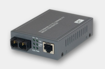
RJ45 (100Base-TX) / Multi-mode SC Fiber (100Base-FX) Media Converter Many networks today are a mixture of fiber optic and copper-based cabling. Using a media converter allows for converting a fiber connections to copper-based cabling or allows extending Cat type network cables great distances.
These 10/100Mbps Auto-Negotiation Fast Ethernet Switching Media Converters provide conversion between 10Base-T Ethernet or 100Base-TX Fast Ethernet UTP (Cat.3 or Cat. 5) cables and 100Base-FX multimode (SC connectors) fiber optic cables.
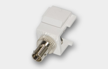
ST Fiber Optic Keystone Module/Coupler Use keystone modules along with keystone wall plates to tidy up your fiber network setup. This product allows you the flexibility and scalability of deploying fiber into any office or room. This module allows you to run an ST-terminated fiber cable in the wall and terminate it at a wall plate.
Digital Audio Optical Fiber — TOSLINK
TOSLINK ("TOShiba-LINK") is a digital optical transmission medium originally created by Toshiba in 1983 for connecting their CD players to receivers. Unlike other fiber, the 1 mm core of TOSLINK cables is typically constructed of inexpensive plastics such as plexiglass. Like other fiber, TOSLINK cables are immune to interference making shielding unnecessary. Additionally, optical audio connections do not suffer from distortion or signal losses from resistance or capacitance unlike copper-based connections.
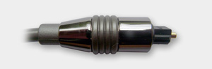
TOSLINK Connector
TOSLINK cables allow for up to 125 Mbps data speeds at lengths up to a maximum 150 feet although this number can be exceeded with signal repeaters or more powerful optical transmitters found in some audio devices. These cables are available with two types of connectors, the standard "square" shaped and a 3.5mm mini-TOSLINK connector found on Apple computers. Apple computers and other manufacturers who use the mini-TOSLINK connection double the use of the jack to output both digital optical and stereo analog audio data. The mini-TOSLINK connector is nearly identical to a stereo 3.5mm (1/8") plug save for that it is 0.5 mm longer in length. This added length is to ensure that standard 3.5mm stereo analog plugs do not come into contact with the fiber's LED transmitter.
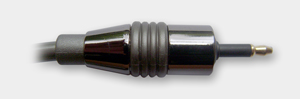
3.5 mm Mini TOSLINK Connector
on Fiber Cross-Section |
on Fiber Cross-Section |

on Fiber Cross-Section |
Care and Feeding of Fiber Optics
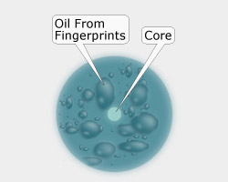
Unlike copper-based cables, fiber optic connections are rarely lost due to cable damage or breakage. However, dust, dirt and other contaminants each have the potential for disrupting or even severing an optical signal. Because fiber cables have such a small core (especially single-mode cables at 9 μm), even a 1-2 μm dust particle will cause significant optical signal loss. Oil too, such as from fingerprints while handling a cable, has the potential to ruin a fiber connection.
Cleaning Connections
Fiber connections can be cleaned with either a wet or a dry cleaning method.
For wet cleaning, fold a piece of lens paper a few times and lay it on a flat
surface. After this, apply a couple of drops of isopropyl alcohol (rubbing
alcohol) to the paper at which point it is ready for cleaning. To clean the
fiber core, hold the connector in a vertical manner and lightly press the end
against the lens paper while moving it in a figure-eight pattern. Repeat this
motion a few times and follow this by removing any solvent build-up with a
lint-free wipe or air dusting.
Dry cleaning a fiber connection is similar to wet cleaning and involves either a lint-free wipe (without adding solvent) or a reel-based fiber connector cleaner. As dry cleaning methods are abrasive in nature, the latter device is recommended as it effectively removes the potential for damaging the core's face by scratching due to a layer of padding below the cleaning surface.
Silly Questions You Were Afraid To Ask
- Q: If fiber optic cable is made of glass, why doesn't it break when bent?
- A: While glass is considered a fragile material, glass optical fiber is quite robust. Pure silica glass in particular, besides offering ultra low optical propagation losses, offers excellent mechanical strength in terms of bending and pulling.
- Q: Do signals travel faster in fiber optic cable than regular copper cable?
- A: No, signals sent over fiber optics travel at about 67% of the speed of light which is around the same speed that a signal would travel in UTP cable such as Cat5e. Coaxial cable allows signals to travel at up to 90% of the speed of light. When people refer to the speed of fiber, they are typically referring to its bandwidth potential which is multiple orders of magnitude greater than copper cabling.
Terms and Definitions
- Attenuation: A gradual diminishing in the strength of signal. A reduction in the level of some property with distance, especially the amplitude of a wave.
- Bandwidth: The width, typically measured in hertz, of a frequency band. The higher the carrier frequency, the more information a signal can hold.
- Buffer coating: A plastic coating that serves to protect the fiber from moisture and damage.
- Cladding: A mirror-like covering surrounding the core that reflects light waves back into it.
- Core: The thin optical glass or plastic center of the fiber where the light travels.
- Coupler: A mechanical device that serves to connect the ends of adjacent objects.
- Crosstalk: Unwanted electrical currents in conductors caused by electromagnetic or electrostatic coupling from other conductors. Also, when a signal on one pair leaks or jumps onto an adjacent pair.
- Dielectric: A material with negligible electrical or thermal conductivity.
- Differential mode delay: When a single light mode transforms into multiple unsynchronized modes causing dispersion of the light and associated losses.
- Doping: Adding an impurity element to a crystal lattice in low concentrations in order to alter the optical/electrical properties of the crystal.
- EMI: Electro Magnetic Interference. An electromagnetic disturbance that degrades or limits the effective performance of electronic or electrical equipment.
- Gallium arsenide "GaAs": A type III/V semiconductor that is used to construct devices such as microwave frequency integrated circuits, infrared light-emitting diodes, laser diodes, and solar cells.
- Graded-index: An optical fiber whose core has a refractive index that decreases with increasing radial distance from the fiber axis which causes light rays to follow sinusoidal paths down the fiber.
- LED: Light Emitting Diode.
- Modal dispersion: A distortion mechanism occurring in multimode fibers and other waveguides, in which the signal is spread in time because the propagation velocity of the optical signal is not the same for all modes.
- Multi-mode: An optical fiber that has a core large enough to propagate more than one mode of light. The typical diameter is 62.5 μm.
- Refractive index: A property of a material that determines how fast light travels through it.
- RFI: Radio Frequency Interference.
- Speed of light "c": The speed of light in a vacuum is exactly 299,792,458 meters per second.
- Single-mode: An optical fiber in which the signal travels in one mode. The fiber has a small core diameter, typically 9 μm.
- Step-index: A refractive index profile characterized by a uniform refractive index within the core and a sharp decrease in refractive index at the core-cladding interface.
- Total internal reflection: An optical phenomenon that occurs when a ray of light strikes a medium boundary at an angle larger than a particular critical angle with respect to the normal to the surface. If the refractive index is lower on the other side of the boundary, no light can pass through and all of the light is reflected.
- VCSEL: Vertical Cavity Surface Emitting Laser.
- Wavelength "λ": The distance between successive crests of a wave. For light, it can denote the color and carries the units nm.